
Negative electrode materials
SAXS & Negative Electrode Material
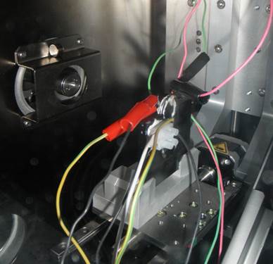
Figure 1 - Experimental Setup
Small-angle X-ray scattering (SAXS) data is taken of coin cells with nanostructured negative electrode materials such as SnCoC. Coin cells are made with Beryllium (transparent to X-rays) windows and are connected via an external cable to chargers in the main lab. X-ray information is collected as these in-situ cells charge and discharge, and the result is modeled and combined with voltage data to give a quantitative look into the behaviour of the nanostructured material upon lithiation and delithiation.
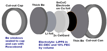
Figure 2
Periodic SAXS data of two lithiation-delithiation cycles. The pattern never returns to that of the fresh material.
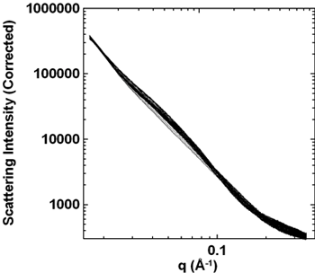
Figure 3
Fade mechanisms in Li-ion cells with Si-alloy containing negative electrodes
Li-ion batteries are now used in a wide variety of applications. However, energy density (amount of energy stored per unit volume) still needs to be improved. As such Si alloy materials are of interest for their high volumetric capacity (≈3 times that of the widely used graphite material).
Li-ion cells that contain Si-based materials typically show rapid capacity fade (amount of Li exchanged from the positive electrode to the negative electrode during one charge or one discharge). Understanding why this rapid capacity fade occurs is of upmost importance.
In order to understand this fade mechanism cells containing a negative electrodes consisting of a blend of Si alloy and graphite and a positive electrode consisting LiCoO2 were filled with the same electrolyte and cycled for various amount of time and various rates (currents of various amplitudes). The electrolyte used contained 10 wt% fluoroethylene carbonate (FEC), an additive that has been widely reported as extending lifetime of cells containing Si-based negative electrodes.
Figure 1a shows the capacity vs. cycle number of cells cycled at C/2 and 20°C. Figure 1a shows that cells present a steady initial capacity fade during the first 350 cycles followed by a sudden failure. In order to understand this fade, the composition of the electrolyte was analyzed by gas chromatography. Figure 1a shows that the cell that underwent 100 cycles had only 5.3% of the additive FEC left out of the initial 10%. Figure 1a also shows that the cell that was stopped right before sudden failure had only 0.9% of the additive left while the cell that was stopped after failure had none left. This clearly shows that the additive is consumed rapidly and that its presence in the electrolyte is necessary for cells to function relatively well. Once the additive runs out, the cell undergoes sudden failure.
Figure 1b shows the cell capacity vs. cycling time for cells that were cycled at various rates. Figure 1b shows that cells cycled the fastest (C/2) show more fade for a given cycling time than cells cycled more slowly. If cycling time was the only factor dictating early capacity fade, cells would have the same capacity fade for a given cycling time regardless of their cycling rate. This indicates that some of the fade in Si-containing cells has a cycle-number dependence. This can be understood from the fact that Si or Si-alloy expand upon lithiation (charge) from 120% to 280% of their initial volume. This large volume expansion induces cracks in the protective layer at the surface of the particles. This protective layer is made via the degradation of the electrolyte which produces compounds that precipitates at the surface of the particles thus protecting the electrolyte from further degradation. The creation of this protective layer consumes active lithium. Each time this protective layer cracks upon particle expansion, more active lithium is consumed to regenerate this protective layer. The consumption of active lithium is at the origin of the capacity fade.
The design of Si-containing cells with long lifetime then needs electrolyte that reduces the consumption rate of FEC or uses another passivating agent, as well as uses a combination of electrolyte composition and active material design that reduces the amount of cracks in the protective layer generated by the expansion of the Si.
For more details, see Petibon et al. Journal of The Electrochemical Society, 163, A1146 (2016)
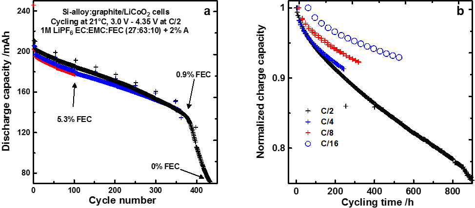
Figure 1 - 200 mAh Si-alloy:graphite/LiCoO2 pouch cells cycled at room temperature and C/2 (a), 200 mAh Si-alloy:graphite/LiCoO2 pouch cells cycled at 40°C and various rates. All cells were filled with an electrolyte containing 10% fluoroethylene carbonate (FEC).